QuickStart
Want a quick glimpse of what CadQuery can do? This quickstart will demonstrate the basics of CadQuery using a simple example
Prerequisites: CadQuery installation
If you want to quickly try out CadQuery you can do so by running apptainer,
apptainer run oras://ghcr.io/cadquery/cadquery-apptainer:master ipython -i your_script.py
or docker/podman. Note that on Windows this will require using WSL.
podman run -it -v /tmp:/tmp -e DISPLAY=$DISPLAY -v $(pwd):/data ghcr.io/cadquery/cadquery-docker:master ipython -i /data/your_script.py
Otherwise, follow the Installing CadQuery, to install CadQuery.
You can use any editor of your choice to edit CadQuery (i.e. Python) scripts. You’ll see that we start out with the script for a simple block.
What we’ll accomplish
We will build a fully parametric bearing pillow block in this quickstart. Our finished object will look like this:

We would like our block to have these features:
It should be sized to hold a single 608 ( ‘skate’ ) bearing, in the center of the block.
It should have counter-bored holes for M2 socket head cap screws at the corners.
The length and width of the block should be configurable by the user to any reasonable size.
A human would describe this as:
“A rectangular block 80mm x 60mm x 10mm , with counter-bored holes for M2 socket head cap screws at the corners, and a circular pocket 22mm in diameter in the middle for a bearing.”
Human descriptions are very elegant, right? Hopefully our finished script will not be too much more complex than this human-oriented description.
Let’s see how we do.
Start With A single, simple Plate
Let’s start with a simple model that makes nothing but a rectangular block, but with place-holders for the dimensions. Add this code to your script file:
 1import cadquery as cq
 2from cadquery.vis import show
 3
 4height = 60.0
 5width = 80.0
 6thickness = 10.0
 7
 8# make the base
 9result = cq.Workplane("XY").box(height, width, thickness)
10
11# Render the solid
12show(result)
Run the script. You should see our base object.
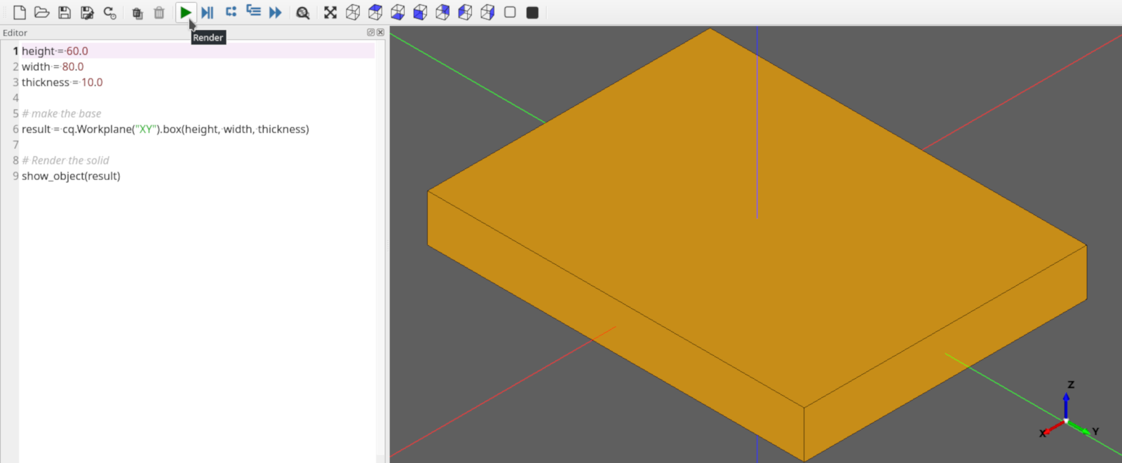
Nothing special, but its a start!
Add the Holes
Our pillow block needs to have a 22mm diameter hole in the center to hold the bearing.
This modification will do the trick:
 1import cadquery as cq
 2from cadquery.vis import show
 3
 4height = 60.0
 5width = 80.0
 6thickness = 10.0
 7diameter = 22.0
 8
 9# make the base
10result = (
11    cq.Workplane("XY")
12    .box(height, width, thickness)
13    .faces(">Z")
14    .workplane()
15    .hole(diameter)
16)
17
18# Render the solid
19show(result)
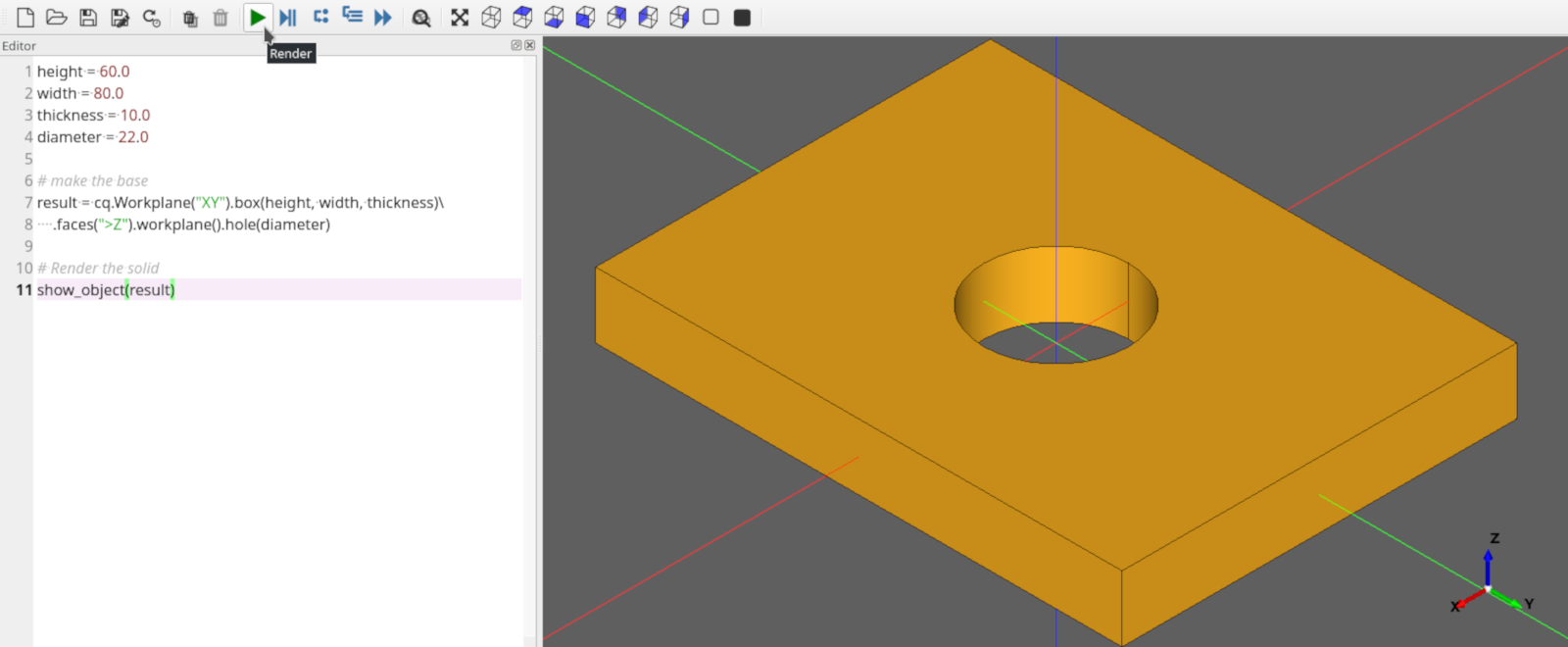
Rebuild your model by rerunning the script. Your block should look like this:
The code is pretty compact, let’s step through it.
Line 7 adds a new parameter, diameter, for the diameter of the hole
Lines 13-15, we’re adding the hole.
cadquery.Workplane.faces() selects the top-most face in the Z direction, and then
cadquery.Workplane.workplane() begins a new workplane located on this face. The center of this workplane
is located at the center of mass of the shape, which in this case is the center of the plate.
Finally, cadquery.Workplane.hole() drills a hole through the part, 22mm in diameter.
Note
Don’t worry about the CadQuery syntax now.. you can learn all about it in the API Reference later.
More Holes
Ok, that hole was not too hard, but what about the counter-bored holes in the corners?
An M2 Socket head cap screw has these dimensions:
Head Diameter : 3.8 mm
Head height : 2.0 mm
Clearance Hole : 2.4 mm
CounterBore diameter : 4.4 mm
The centers of these holes should be 6mm from the edges of the block. And, we want the block to work correctly even when the block is re-sized by the user.
Don’t tell me we’ll have to repeat the steps above 8 times to get counter-bored holes? Good news!– we can get the job done with just a few lines of code. Here’s the code we need:
 1import cadquery as cq
 2from cadquery.vis import show
 3
 4height = 60.0
 5width = 80.0
 6thickness = 10.0
 7diameter = 22.0
 8padding = 12.0
 9
10# make the base
11result = (
12    cq.Workplane("XY")
13    .box(height, width, thickness)
14    .faces(">Z")
15    .workplane()
16    .hole(diameter)
17    .faces(">Z")
18    .workplane()
19    .rect(height - padding, width - padding, forConstruction=True)
20    .vertices()
21    .cboreHole(2.4, 4.4, 2.1)
22)
23# Render the solid
24show(result)
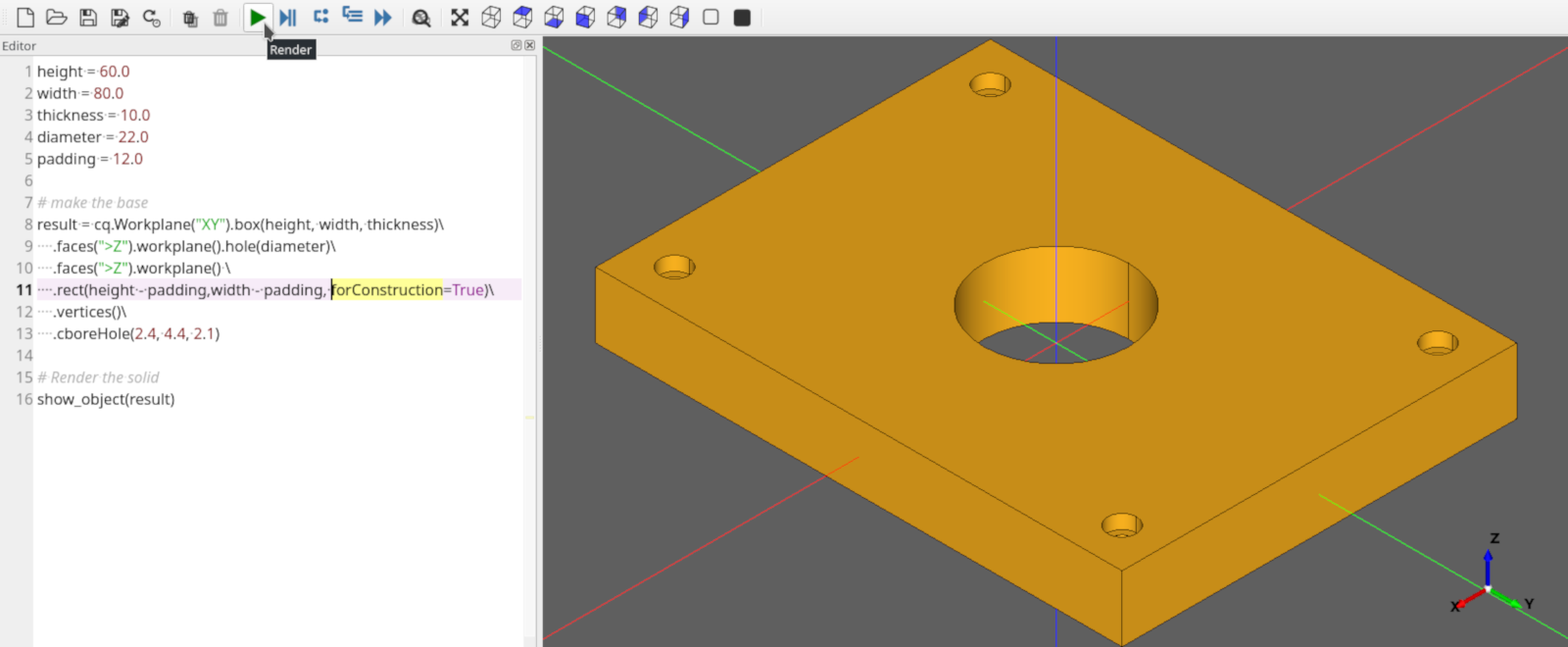
After running the script again, you should see something like this:
There is quite a bit going on here, so let’s break it down a bit.
Line 8 creates a new padding parameter that decides how far the holes are from the edges of the plate.
Lines 17-18 selects the top-most face of the block, and creates a workplane on the top of that face, which we’ll use to define the centers of the holes in the corners.
Line 19 draws a rectangle 12mm smaller than the overall length and width of the block, which we will use to locate the corner holes. We’ll use the vertices ( corners ) of this rectangle to locate the holes. The rectangle’s center is at the center of the workplane, which in this case coincides with the center of the bearing hole.
There are a couple of things to note about this line:
The
cadquery.Workplane.rect()function draws a rectangle. forConstruction=True tells CadQuery that this rectangle will not form a part of the solid, but we are just using it to help define some other geometry.Unless you specify otherwise, a rectangle is drawn with its center on the current workplane center– in this case, the center of the top face of the block. So this rectangle will be centered on the face.
Line 20 selects the vertices of the rectangle, which we will use for the centers of the holes.
The cadquery.Workplane.vertices() function selects the corners of the rectangle.
Line 21 uses the cboreHole function to draw the holes.
The cadquery.Workplane.cboreHole() function is a handy CadQuery function that makes a counterbored hole.
Like most other CadQuery functions, it operates on the values on the stack. In this case, since we
selected the four vertices before calling the function, the function operates on each of the four points–
which results in a counterbore hole at each of the rectangle corners.
Filleting
Almost done. Let’s just round the corners of the block a bit. That’s easy, we just need to select the edges and then fillet them:
We can do that using the preset dictionaries in the parameter definition:
 1import cadquery as cq
 2from cadquery.vis import show
 3
 4height = 60.0
 5width = 80.0
 6thickness = 10.0
 7diameter = 22.0
 8padding = 12.0
 9
10# make the base
11result = (
12    cq.Workplane("XY")
13    .box(height, width, thickness)
14    .faces(">Z")
15    .workplane()
16    .hole(diameter)
17    .faces(">Z")
18    .workplane()
19    .rect(height - padding, width - padding, forConstruction=True)
20    .vertices()
21    .cboreHole(2.4, 4.4, 2.1)
22    .edges("|Z")
23    .fillet(10.0)
24)
25
26# Render the solid
27show(result)
Line 22 To grab the right edges, the cadquery.Workplane.edges() selects all of the
edges that are parallel to the Z axis (”|Z”).
Line 23 fillets the edges using the cadquery.Workplane.fillet() method.
The finished product looks like this:
Exporting
If you want to fabricate a physical object you need to export the result to STL or DXF. Additionally, exporting as STEP for post-processing in another CAD tool is also possible.
This can be easily accomplished using the cadquery.Workplane.export() function:
Done!
You just made a parametric, model that can generate pretty much any bearing pillow block with <30 lines of code.
Free function equivalent
If the fluent style of modeling does not appeal to you, note that exactly the same object can be constructed using Free function API.
 1from cadquery.func import *
 2
 3height = 60.0
 4width = 80.0
 5thickness = 10.0
 6diameter = 22.0
 7padding = 12.0
 8r_hole = 1.2
 9r_cbore = 2.2
10d_cbore = thickness / 3
11
12# construct hole locations
13hole_locs = rect(height - padding, width - padding).vertices()
14
15# make the base
16basef = face(
17   rect(height, width),
18   circle(diameter / 2),
19)
20
21# extrude
22base = extrude(basef, (0, 0, thickness))
23
24# fillet
25base = fillet(base, base.edges("|Z"), height / 10)
26
27# add a cbore
28top = base.face(">Z")
29base = prism(base, None, circle(r_cbore).moved(hole_locs).moved(top), -d_cbore, additive=False)
30base = prism(base, None, circle(r_hole).moved(hole_locs).moved(top), None, additive=False)
Want to learn more?
The Examples contains lots of examples demonstrating cadquery features
The API Reference is a good overview of language features grouped by function
The CadQuery Class Summary is the hard-core listing of all functions available.