Concepts
3D BREP Topology Concepts
Before talking about CadQuery, it makes sense to talk a little about 3D CAD topology. CadQuery is based upon the OpenCascade kernel, which uses Boundary Representations (BREP) for objects. This just means that objects are defined by their enclosing surfaces.
When working in a BREP system, these fundamental constructs exist to define a shape (working up the food chain):
- vertex:
a single point in space
- edge:
a connection between two or more vertices along a particular path (called a curve)
- wire:
a collection of edges that are connected together.
- face:
a set of edges or wires that enclose a surface
- shell:
a collection of faces that are connected together along some of their edges
- solid:
a shell that has a closed interior
- compound:
a collection of solids
When using CadQuery, all of these objects are created, hopefully with the least possible work. In the actual CAD kernel, there is another set of Geometrical constructs involved as well. For example, an arc-shaped edge will hold a reference to an underlying curve that is a full circle, and each linear edge holds underneath it the equation for a line. CadQuery shields you from these constructs.
CadQuery API layers
Once you start to dive a bit more into CadQuery, you may find yourself a bit confused juggling between different types of objects the CadQuery APIs can return. This chapter aims to give an explanation on this topic and to provide background on the underlying implementation and kernel layers so you can leverage more of CadQuery functionality.
CadQuery is composed of 4 different API, which are implemented on top of each other.
- The Free Function API
The OCCT API
The Fluent API
What we call the fluent API is what you work with when you first start using CadQuery, the Workplane class and all its methods defines the Fluent API.
This is the API you will use and see most of the time, it’s fairly easy to use and it simplifies a lot of things for you. A classic example could be :
part = Workplane("XY").box(1, 2, 3).faces(">Z").vertices().circle(0.5).cutThruAll()
Here we create a Workplane object on which we subsequently call several methods to create our part. A general way of thinking about the Fluent API is to
consider the Workplane as your part object and all it’s methods as operations that will affect your part.
Often you will start with an empty Workplane, then add more features by calling Workplane methods.
This hierarchical structure of operations modifying a part is well seen with the traditional code style used in CadQuery code. Code written with the CadQuery fluent API will often look like this :
part = Workplane("XY").box(1, 2, 3).faces(">Z").vertices().circle(0.5).cutThruAll()
Or like this :
part = Workplane("XY")
part = part.box(1, 2, 3)
part = part.faces(">Z")
part = part.vertices()
part = part.circle(0.5)
part = part.cutThruAll()
Note
While the first code style is what people default to, it’s important to note that when you write your code like this it’s equivalent as writting it on a single line. It’s then more difficult to debug as you cannot visualize each operation step by step, which is a functionality that is provided by the CQ-Editor debugger for example.
The Free Function API
While the fluent API exposes much functionality, you may find scenarios that require extra flexibility or require working with lower level objects.
The free function API is the API that is called by the fluent API under the hood. The 9 topological classes, their methods and additional free functionsi compose the free function API. These classes actually wrap the equivalent Open CASCADE Technology (OCCT) classes. The 9 topological classes are :
Each class has its own methods to query, select and position shapes. On the other hand, one can use free function to create and modify shapes. As already explained in Concepts there is also some kind of hierarchy in the topological classes. A Wire is made of several edges which are themselves made of several vertices. This means you can create geometry from the bottom up and have a lot of control over it.
For example we can create a circular face like so
.. code-block:: python
circle_wire = wire(circle(1)) circular_face = face(circle_wire)
Note
In CadQuery (and OCCT) all the topological classes are shapes, the Shape class is the most abstract topological class.
The topological class inherits Mixin3D or Mixin1D which provide additional methods that are shared between the classes that inherits them.
The OCCT API
Finally we are discussing about the OCCT API. The OCCT API is the lowest level of CadQuery. The direct API is built upon the OCCT API, where the OCCT API in CadQuery is available through OCP. OCP are the Python bindings of the OCCT C++ libraries CadQuery uses. This means you have access to (almost) all the OCCT C++ libraries in Python and in CadQuery. Working with the OCCT API will give you the maximum flexibility and control over you designs, it is however very verbose and difficult to use. You will need to have a strong knowledge of the different C++ libraries to be able to achieve what you want. To obtain this knowledge the most obvious ways are :
Read the direct API source code, since it is build upon the OCCT API it is full of example usage.
Go through the C++ documentation
Note
The general way of importing a specific class of the OCCT API is
from OCP.thePackageName import theClassName
For example if you want to use the class BRepPrimAPI_MakeBox. You will go by the following
from OCP.BRepPrimAPI import BRepPrimAPI_MakeBox
The package name of any class is written at the top of the documentation page. Often it’s written in the class name itself as a prefix.
Going back and forth between the APIs
While the 3 APIs provide 3 different layer of complexity and functionality you can mix the 3 layers as you wish. Below is presented the different ways you can interact with the different API layers.
Fluent API <=> Free Function API
Here are all the possibilities you have to get an object from the free function API (i.e a topological object).
You can end the Fluent API call chain and get the last object on the stack with Workplane.val() alternatively you can get all
the objects with Workplane.vals()
>>> box = Workplane().box(10, 5, 5)
>>> print(type(box))
<class cadquery.cq.Workplane>

>>> box = Workplane().box(10, 5, 5).val()
>>> print(type(box))
<class cadquery.occ_impl.shapes.Solid>
If you are only interested in getting the context solid of your Workplane, you can use Workplane.findSolid():
>>> part = Workplane().box(10,5,5).circle(3).val()
>>> print(type(part))
<class cadquery.cq.Wire>

>>> part = Workplane().box(10,5,5).circle(3).findSolid()
>>> print(type(part))
<class cadquery.occ_impl.shapes.Compound>
# The return type of findSolid is either a Solid or a Compound object
If you want to go the other way around i.e using objects from the topological API in the Fluent API here are your options :
You can pass a topological object as a base object to the Workplane object.
solid_box = box(10, 10, 10)
part = Workplane(obj=solid_box)
# And you can continue your modelling in the fluent API
part = part.faces(">Z").circle(1).extrude(10)
You can add a topological object as a new operation/step in the Fluent API call chain with Workplane.newObject()
circle_wire = wire(circle(1.0))
box = Workplane().box(10, 10, 10).newObject([circle_wire])
# And you can continue modelling
box = (
    box.toPending().cutThruAll()
)  # notice the call to `toPending` that is needed if you want to use it in a subsequent operation
Free Function API <=> OCCT API
Every object of the free function API stores its OCCT equivalent object in its wrapped attribute.:
>>> box = box(10,5,5)
>>> print(type(box))
<class cadquery.occ_impl.shapes.Solid>

>>> box = box(10,5,5).wrapped
>>> print(type(box))
<class OCP.TopoDS.TopoDS_Solid>
If you want to cast an OCCT object into a free function API one you can just pass it as a parameter of the intended class:
>>> occt_box = BRepPrimAPI_MakeBox(5,5,5).Solid()
>>> print(type(occt_box))
<class OCP.TopoDS.TopoDS_Solid>

>>> direct_api_box = Solid(occt_box)
>>> print(type(direct_api_box))
<class cadquery.occ_impl.shapes.Solid>
Note
You can cast into the direct API the types found here
Multimethods
CadQuery uses Multimethod to allow a call to a method to
be dispatched depending on the types of the arguments. An example is arc(),
where a_sketch.arc((1, 2), (2, 3)) would be dispatched to one method but a_sketch.arc((1, 2),
(2, 3), (3, 4)) would be dispatched to a different method. For multimethods to work, you should
not use keyword arguments to specify positional parameters. For example, you should not write
a_sketch.arc(p1=(1, 2), p2=(2, 3), p3=(3, 4)), instead you should use the previous example.
Note CadQuery makes an attempt to fall back on the first registered multimethod in the event of a
dispatch error, but it is still best practice to not use keyword arguments to specify positional
arguments in CadQuery.
Selectors
Selectors allow you to select one or more features, in order to define new features. As an example, you might extrude a box, and then select the top face as the location for a new feature. Or, you might extrude a box, and then select all of the vertical edges so that you can apply a fillet to them.
You can select Vertices, Edges, Faces, Solids, and Wires using selectors.
Think of selectors as the equivalent of your hand and mouse, if you were to build an object using a conventional CAD system.
See Selectors to learn more.
Workplane class
The Workplane class contains the currently selected objects (a list of Shapes, Vectors or Locations
in the objects attribute), the modelling context (in the
ctx attribute), and CadQuery’s fluent api methods. It is the main class
that users will instantiate.
See API Reference to learn more.
Assemblies
Simple models can be combined into complex, possibly nested, assemblies.
A simple example could look as follows:
from cadquery import *

w = 10
d = 10
h = 10

part1 = Workplane().box(2 * w, 2 * d, h)
part2 = Workplane().box(w, d, 2 * h)
part3 = Workplane().box(w, d, 3 * h)

assy = (
    Assembly(part1, loc=Location(Vector(-w, 0, h / 2)))
    .add(
        part2, loc=Location(Vector(1.5 * w, -0.5 * d, h / 2)), color=Color(0, 0, 1, 0.5)
    )
    .add(part3, loc=Location(Vector(-0.5 * w, -0.5 * d, 2 * h)), color=Color("red"))
)
Resulting in:
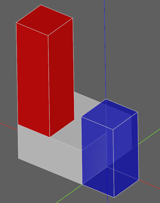
Note that the locations of the children parts are defined with respect to their parents - in the above example part3 will be located at (-5,-5,20) in the global coordinate system. Assemblies with different colors can be created this way and exported to STEP or the native OCCT xml format.
You can browse assembly related methods here: Assemblies.
Assemblies with constraints
Sometimes it is not desirable to define the component positions explicitly but rather use constraints to obtain a fully parametric assembly. This can be achieved in the following way:
from cadquery import *

w = 10
d = 10
h = 10

part1 = Workplane().box(2 * w, 2 * d, h)
part2 = Workplane().box(w, d, 2 * h)
part3 = Workplane().box(w, d, 3 * h)

assy = (
    Assembly(part1, name="part1", loc=Location(Vector(-w, 0, h / 2)))
    .add(part2, name="part2", color=Color(0, 0, 1, 0.5))
    .add(part3, name="part3", color=Color("red"))
    .constrain("part1@faces@>Z", "part3@faces@<Z", "Axis")
    .constrain("part1@faces@>Z", "part2@faces@<Z", "Axis")
    .constrain("part1@faces@>Y", "part3@faces@<Y", "Axis")
    .constrain("part1@faces@>Y", "part2@faces@<Y", "Axis")
    .constrain("part1@vertices@>(-1,-1,1)", "part3@vertices@>(-1,-1,-1)", "Point")
    .constrain("part1@vertices@>(1,-1,-1)", "part2@vertices@>(-1,-1,-1)", "Point")
    .solve()
)
This code results in identical object as one from the previous section. The added
benefit is that with changing parameters w, d, h the final locations
will be calculated automatically. It is admittedly dense and can be made clearer
using tags. Tags can be directly referenced when constructing the constraints:
from cadquery import *

w = 10
d = 10
h = 10

part1 = Workplane().box(2 * w, 2 * d, h)
part2 = Workplane().box(w, d, 2 * h)
part3 = Workplane().box(w, d, 3 * h)

part1.faces(">Z").edges("<X").vertices("<Y").tag("pt1")
part1.faces(">X").edges("<Z").vertices("<Y").tag("pt2")
part3.faces("<Z").edges("<X").vertices("<Y").tag("pt1")
part2.faces("<X").edges("<Z").vertices("<Y").tag("pt2")

assy1 = (
    Assembly(part1, name="part1", loc=Location(Vector(-w, 0, h / 2)))
    .add(part2, name="part2", color=Color(0, 0, 1, 0.5))
    .add(part3, name="part3", color=Color("red"))
    .constrain("part1@faces@>Z", "part3@faces@<Z", "Axis")
    .constrain("part1@faces@>Z", "part2@faces@<Z", "Axis")
    .constrain("part1@faces@>Y", "part3@faces@<Y", "Axis")
    .constrain("part1@faces@>Y", "part2@faces@<Y", "Axis")
    .constrain("part1?pt1", "part3?pt1", "Point")
    .constrain("part1?pt2", "part2?pt2", "Point")
    .solve()
)
The following constraints are currently implemented:
- Axis:
two normal vectors are anti-coincident or the angle (in radians) between them is equal to the specified value. Can be defined for all entities with consistent normal vector - planar faces, wires and edges.
- Point:
two points are coincident or separated by a specified distance. Can be defined for all entities, center of mass is used for lines, faces, solids and the vertex position for vertices.
- Plane:
combination of :Axis: and :Point: constraints.
For a more elaborate assembly example see Assemblies.